Pdf Avtech 4ch Mpeg4 Dvr Manual
Fri, 02 Nov 2018 00:14:00. GMT avtech 4ch mpeg4 dvr manual pdf - Avtech 4ch. Mpeg4 Dvr Manual Pdf. View and Download. Avtech AVC796 user manual. DR040ASV_DR040_Manual_V1.05 MPEG4 4CH DVR MANUAL L Please read instructions thoroughly before operation and retain it for future reference. MANUAL List the information of the manual-re corded files. The DVR will save one recorded file once any recording setting is cha nged.
1) LED Indication The following LEDs will be on when: HDD: HDD is reading or recording HDD Full: HDD is full. ALARM: Once the alarm is triggered TIMER: When timer recording is turned on PLAY: Under playing status REC: Under recording status 2) MENU Press this button to enter / exit the DVR menu mode. In the sub-layer of the DVR menu, press this button to confirm the settings and go back to the upper layer.

3) ENTER Confirm the password entering. 4) REC Press this button to activate manual recording. 5) LIST (Event List Search) To quick search the recorded files by event list, press this button to show all types of the event lists. Select one of the event list and press “ENTER” button to playback the selected file.
• User Manual Intelligent Video Surveillance GUI Display with USB Mouse Control Please read instructions thoroughly before operation and retain it for future reference. For the actual display & operation, please refer to your DVR in hand. DVR- AVC 799_794 Manual. • IMPORTANT SAFEGUARD CAUTION RISK OF ELECTRIC SHOCK CAUTION: To reduce the risk of electric shock, do not expose this apparatus to rain or moisture. Only operate this apparatus from the type of power source indicated on the label. The company shall not be liable for any damages arising out of any improper use, even if we have been advised of the possibility of such damages.
• GPL Licensing This product contains codes which are developed by Third-Party-Companies and which are subject to the GNU General Public License (“GPL”) or the GNU Lesser Public License (“LGPL”). The GPL Code used in this product is released without warranty and is subject to the copyright of the corresponding author. • TABLE OF CONTENTS 1.
BEFORE USING THIS DVR.. 1 1.1 Package Content..1 1.2 Front Panel..1 1.3 Rear Panel..2 2. CONNECTION AND SETUP..4 2.1 SATA HDD Installation..4 2.2 Camera Connection..5 2.2.1 Normal Camera Connection..5 2.2.2 DCCS Camera Connection..5 2.2.3 PTZ Camera Connection..5 2.3 DVR Power On..7 2.4 Date and Time Setting..7. General Operation..37 6.1.4.
E-Map..39 6.2 IE Web Browser..45 6.2.1 Event Playback & Download..47 6.2.2 IVS Statistics..48 APPENDIX 1 SPECIFICATIONS..49 APPENDIX 2 PIN CONFIGURATION.53 APPENDIX 3 COMPATIBLE USB FLASH DRIVE LIST.56 APPENDIX 4 COMPATIBLE SATA HDD LIST.57 APPENDIX 5 MAIN MENU STRUCTURE.. • Press to quickly search the recorded files by event lists: RECORD / MOTION / ALARM / TIME / HUMAN DETECTION / IVS / STATISTIC, or select FULL LIST to show all the event logs. To quickly search the time you want, select “QUICK SEARCH”. For details, please refer to “5.4.1 QUICK SEARCH”.
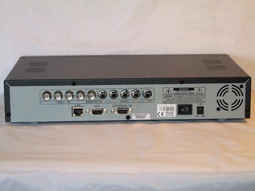
• BEFORE USING THIS DVR (▲) / (▼) / (◄) / (►) Press ▲ / ▼ / ◄ / ► to move up / down / left / right. In the playback mode: Press “ ” to pause playback. Press “ ” to stop playback. • BEFORE USING THIS DVR CALL Connect to a monitor specific for sequence display. Connect to a LCD monitor directly. Note: When both MONITOR and VGA are connected, press the right key ► on the DVR front panel during DVR power-on to force the video output via VGA. For details, please refer to “5.5.6 DISPLAY” at page 25.
• CONNECTION AND SETUP 2. CONNECTION AND SETUP Before the DVR is powered on, make sure you have installed a hard disk and connected at least one camera. For details, please refer to the following sections. Note: The DVR is designed to automatically detect the video system of the connected cameras (NTSC or PAL). • CONNECTION AND SETUP Step5: Replace the top cover and fasten the screws you loosened in Step1. Download omron plc password unlocker software.
2.2 Camera Connection The cameras must be connected and power-supplied before the DVR is powered on. Connect the camera with the indicated power supply. Then, connect the camera video output to the DVR video input port with a coaxial cable or RCA cable with BNC connectors. • CONNECTION AND SETUP setting to control the PTZ camera, please refer to “5.5.7 RECORD” at page 26. For detailed PTZ camera control and operation, please refer to its own user manual. RJ11 cable RS485-A: Red wire RS485-B: Green wire The RJ11 cable is not supplied in the sales package.
Measurement Studio is the only set of.NET tools designed for building engineering applications in Microsoft Visual Studio to acquire, analyze, and display measurement data. You can present data clearly with engineering UI controls that are compatible with hardware-acquired data types. National instruments measurement studio crack.